Electrical Design Outline
The electrical design could be divided into 5 functional sections: Tape Sensor, Coin Sensor, IR Sensor, Driving Motor Control, Power Supply and Shooter Motor and Servo .
The microcontroller used for the project was a Texas Instruments Tiva C Series LaunchPad.
The microcontroller used for the project was a Texas Instruments Tiva C Series LaunchPad.
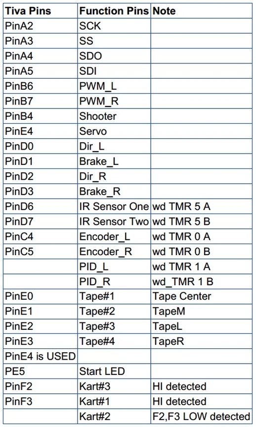
Pin Table
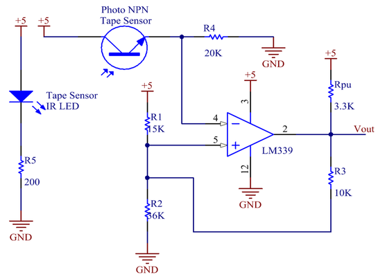
Tape Sensor
Tape sensor is used to detected the black tape, which the vehicle follows to complete a lap of racing. There are four tape sensors mounted on the bottom of the vehicle.
A comparator (LM339) is used for each tape sensor to transfer the analog input into digital output. When the black tape is sensed, the Tiva board receives a HIGH from Vout.
A comparator (LM339) is used for each tape sensor to transfer the analog input into digital output. When the black tape is sensed, the Tiva board receives a HIGH from Vout.
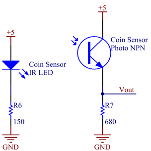
Coin Sensor
Coin Sensor is used to get the signals from the encoder disk mounted on each wheel shaft. Wheel speed could be computed with the periods between rising edges of Vout.
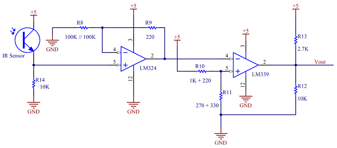
IR Sensor
IR sensor is used to target a beacon 7 feet away, which emits IR signals with 1.25 kHz. When the vehicle succeeds in targeting the beacon, a shooting action could be performed to shoot a ball into the bucket below the beacon.
The analog input from IR sensor is firstly amplified with an amplifier (LM324), then transformed into digital signals with a comparator (LM339).
The analog input from IR sensor is firstly amplified with an amplifier (LM324), then transformed into digital signals with a comparator (LM339).
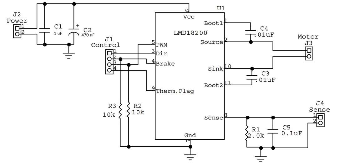
Driving Motor Control
Two LMD18200 H bridge circuits are used to drive the two wheel motors for the KART separately. The power supply is 14.4 V and the Control Pins are directly connected to the Tiva Pins respectively.
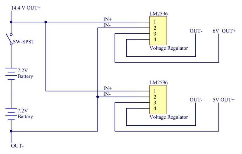
Power Supply
The power supply circuit uses two batteries with 7.2 V in series and two LM2596 regulators to source 6V and 5V DC power to the components. Here, 6V DC is just for Tiva board and 5V DC is for the other components.
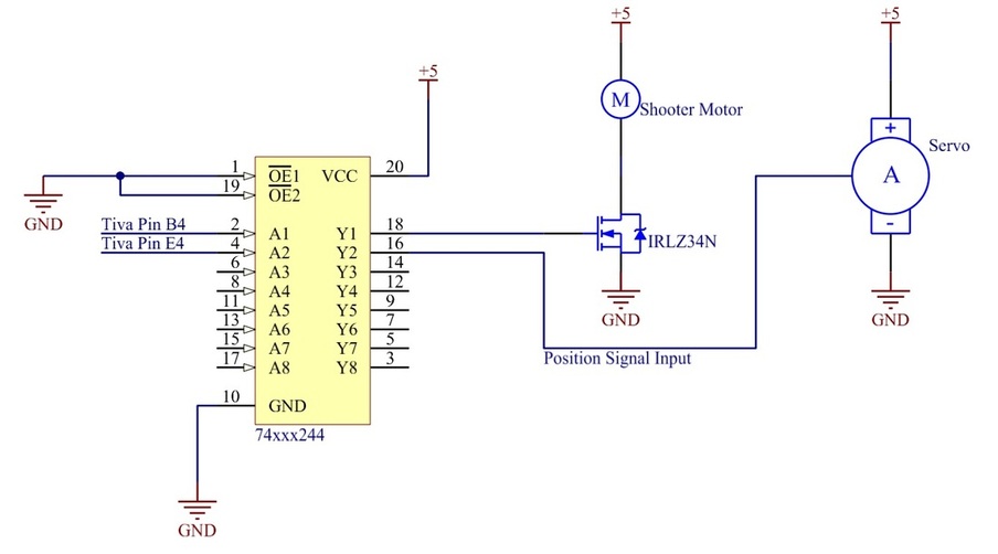
Shooter Motor and Servo
The shooter motor and servo are powered by 5V. The shooter motor is controlled by a IRLZ34N, MOSFET. The signal from Tiva to control the IRLZ34N goes through a 74ACT244 buffer. Also the position signal from Tiva to servo goes through the buffer too.
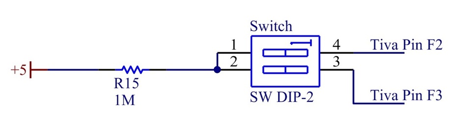
Kart Selection
Here, we use two pins from Tiva, PF2, PF3. When PF2 detects HI voltage, Kart #3 is chosen. When PF3 detects HI voltage, Kart#1 is chosen. When PF2 and PF3 both detects LOW ground, Kart#2 is chosen.
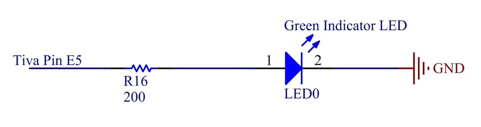
Game Start Indicator
We use a green LED from the lab. The current for it is around 20 mA and Tiva pin can source 25 mA so we use Tiva Pin E5 directly sourcing the LED through a 200 Ohms resistor (The current is around 17 mA, and the LED works) .