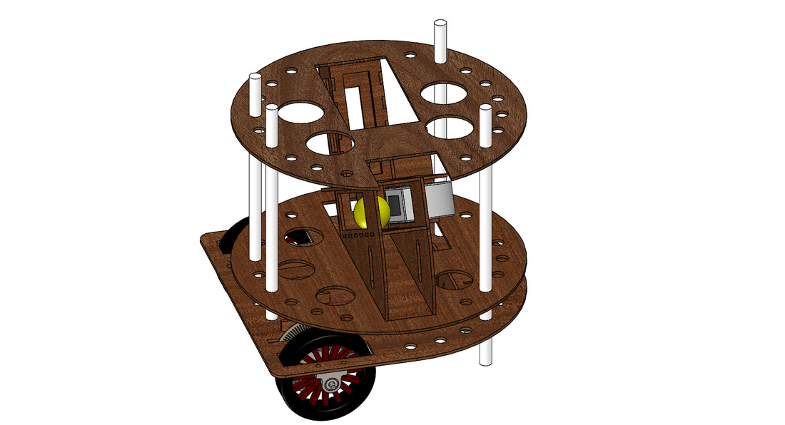
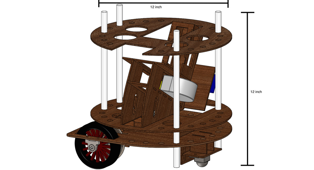
Overall Assembly
Our cart mainly has three plate, the drivetrain plate, the shooting plate and the top plate. The drivetrain plate carries the electrical to mechanical power transmission system, and batteries and most of circuits are placed on top of the drivetrain plate. The shooting plate carries the ball shooting and feeding mechanism, and rest of the circuits are place on the shooting plate. The top plate carries the DrEd Reckoning System and the IR sensor for shooter alignment.
Four 1-inch Nylon threaded rods were used to connect these three plates and support the overall structure. Height of each plate could be adjusted by moving the locking nuts on the threaded rods.
Most of the fabrication was done using laser cutting. Plates and parts were put together using mechanical joints and adhesives.


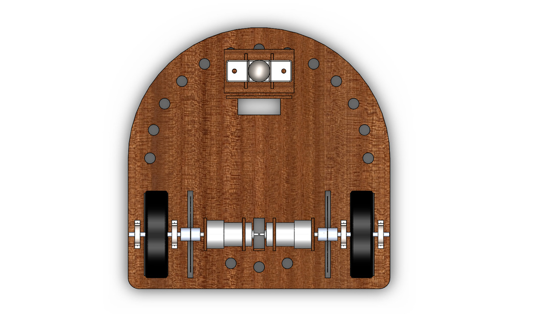
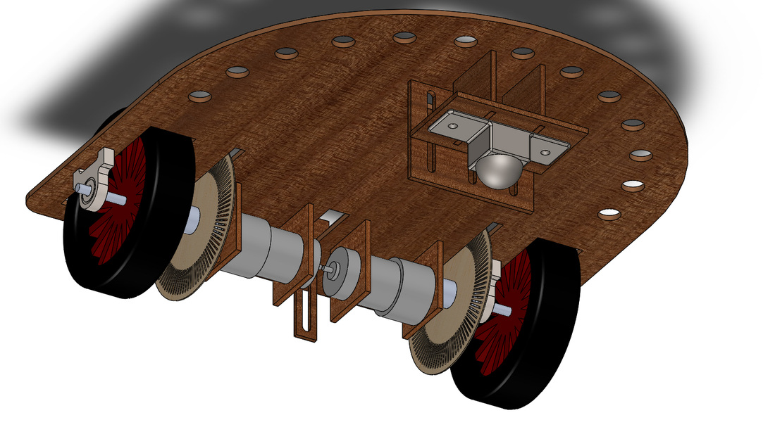
Drivetrain Design
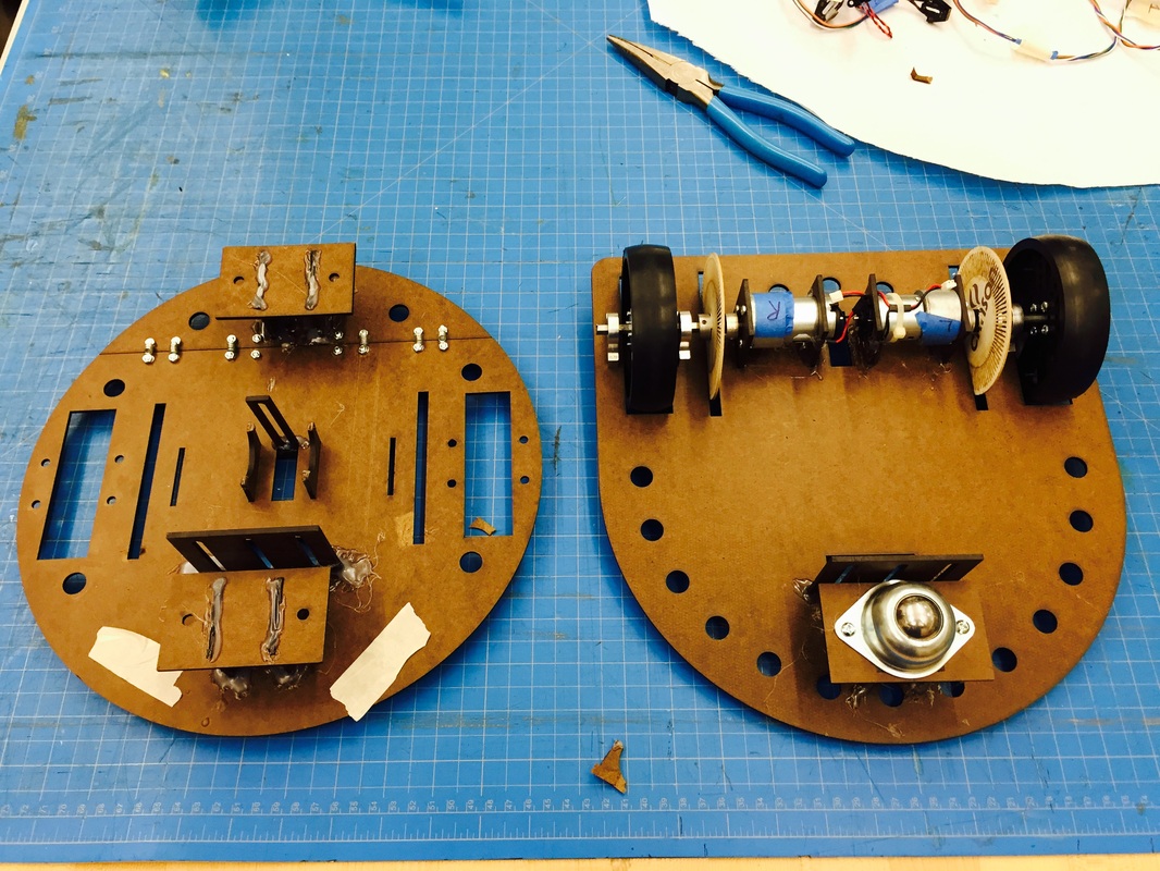
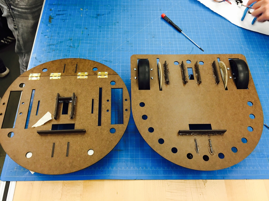
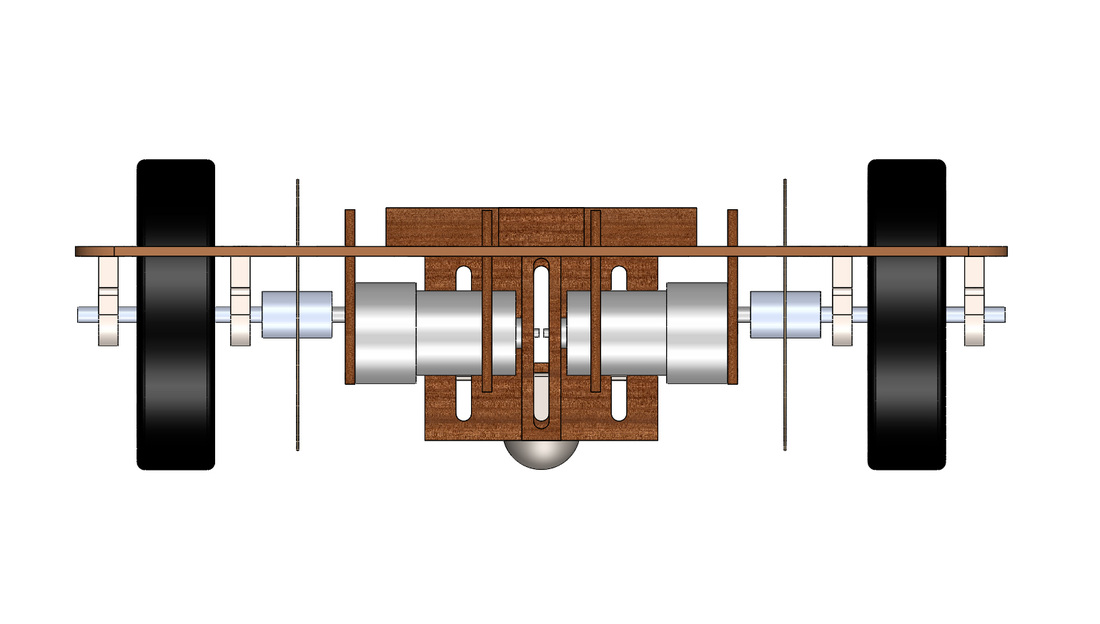
The drivetrain plate carries a ball caster and fixture to support it, two fixtures for tape sensor installation, and the complete drivetrain transmission system on each side.
Each drivetrain system includes a wheel, two bearings, a coupler, an encoder fixed on the coupler, a motor and two fixture plates to support the motor.
Each drivetrain system includes a wheel, two bearings, a coupler, an encoder fixed on the coupler, a motor and two fixture plates to support the motor.
Shooting and Feeding Mechanism
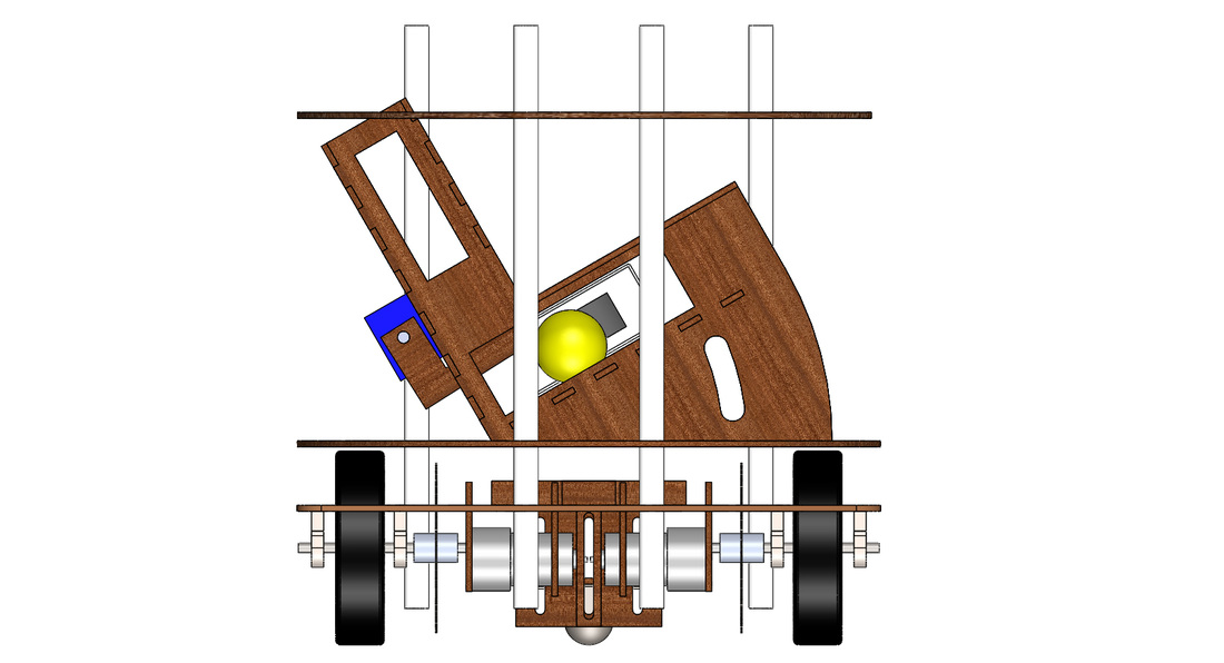
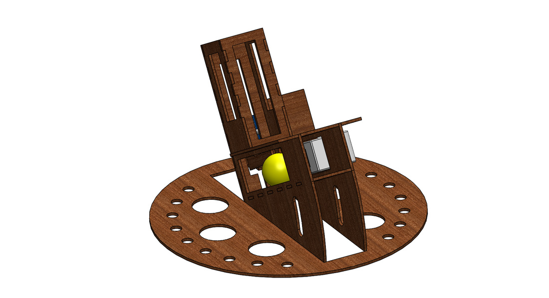
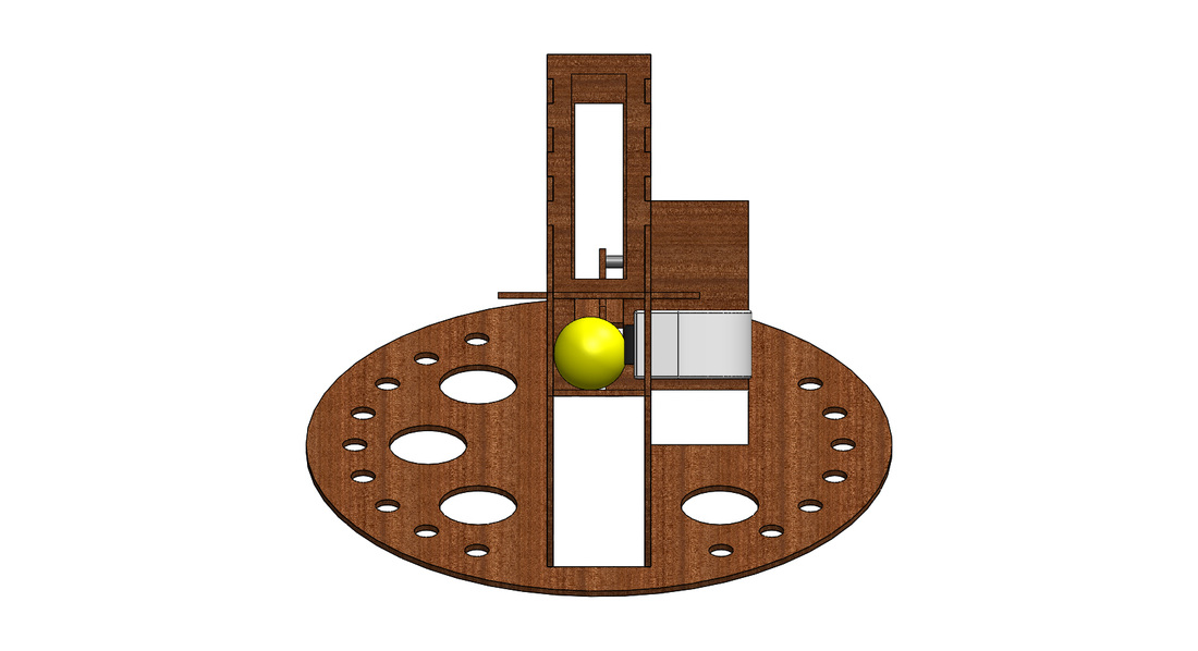
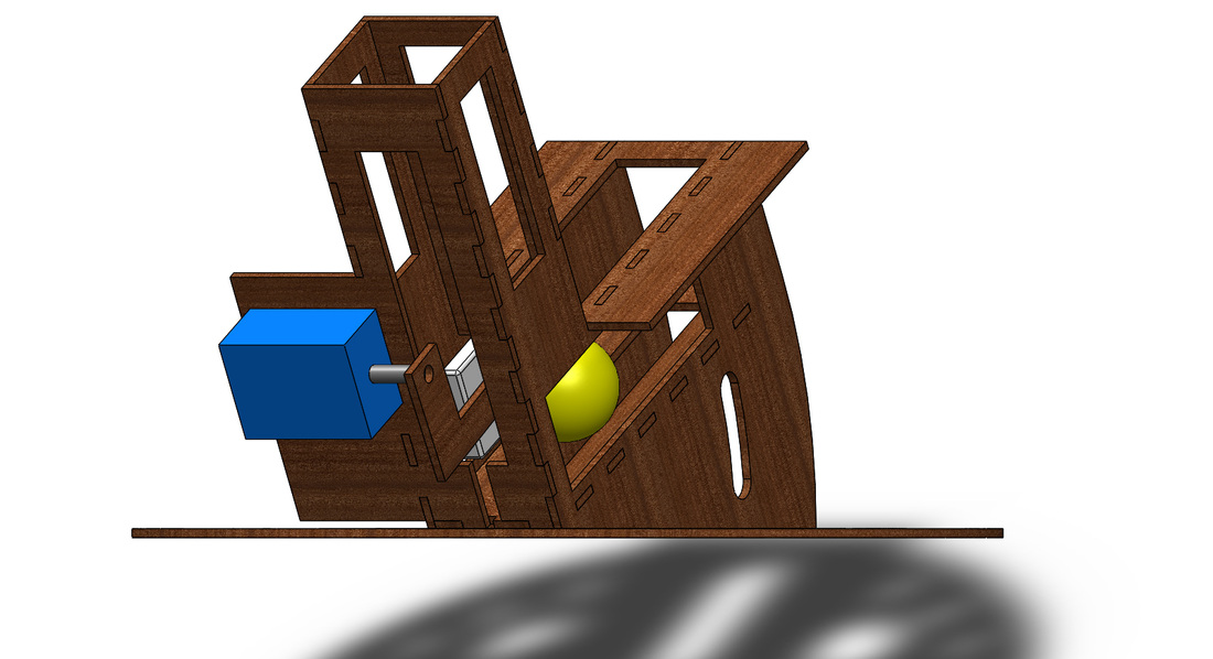
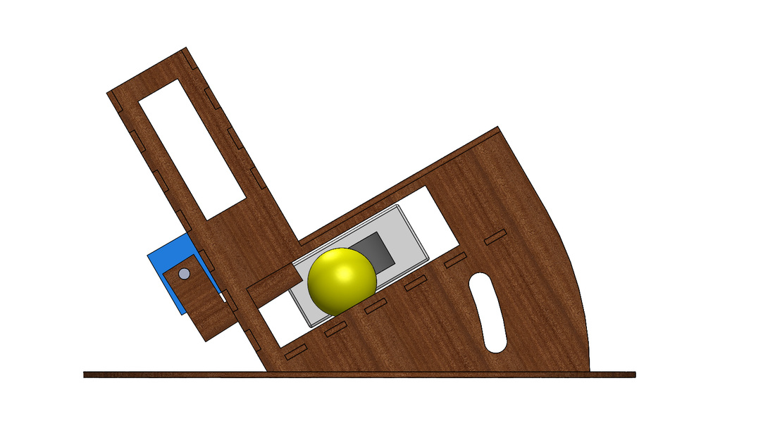
The DC-motor wheel was the key component in the shooting mechanism. When in shooting motion, a ball would be fed to the spinning DC wheel by a L-shaped kicker, that was controlled by a servo. The ball would be slightly squeezed between the wheel and the wall on the other side, so that acceleration would be created.
Three main factors, height of the shooter, initial shooting angle and speed of the wheel, were adjusted in order control the trajectory of the ball. The angle of shooting can be adjusted by sliding the shooter through the slots on the shooting plates.
Three main factors, height of the shooter, initial shooting angle and speed of the wheel, were adjusted in order control the trajectory of the ball. The angle of shooting can be adjusted by sliding the shooter through the slots on the shooting plates.
Design Iterations
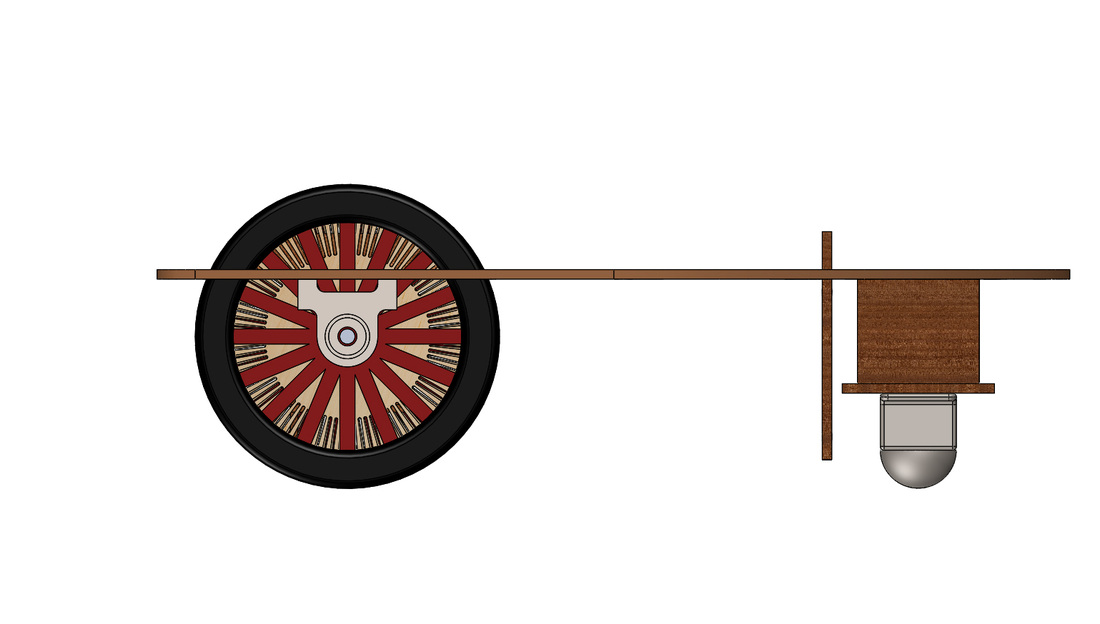
Our original drivetrain design consisted two wheel and two ball casters. One of the ball caster was installed on a simple suspension system, that were basically two plates connected using four hinges and springs. The suspension system was designed to prevent the two driving wheels from being suspended during climbing the seesaw. The ball caster would be lifted, but constrained by the spring, in order to create a three-point contact during climbing motion.
However, due to the height of center of gravity of our cart, the cart tended to turnover on the seesaw. After several trials, we re-designed the drivetrain with only three wheels to balance the cart on both flat surface and slope.
However, due to the height of center of gravity of our cart, the cart tended to turnover on the seesaw. After several trials, we re-designed the drivetrain with only three wheels to balance the cart on both flat surface and slope.